RadioLink | SKU:
RLKR121001
10% off
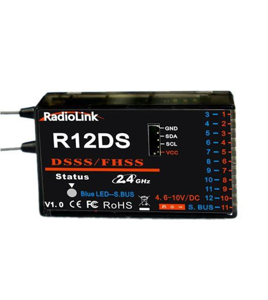
RadioLink R12DS 12 Channel SBUS Receiver. AT9/AT10
£30.58
£33.99
Unit price
/
Unavailable
Tax included
Shipping calculated at checkout.
RadioLink R12DS 12 Channel SBUS Receiver. AT9/AT10 will be backordered from our supplier. Delivery will take between 3-5 working days & orders will be despatched once completed.
Description
Description
Radiolink R12DS, 2.4G 12 channels receiver, DSSS and FHSS spread spectrum work simultaneously, compatible with Radiolink transmitters AT9, AT9S, AT10 and AT10II(AT9, AT9S, AT10 and AT10II can upgrade to 12 channels by just upgrading the firmware, you can download the firmware from the RadioLink website: www.radiolink.com).
Radiolink R12DS, 2.4G 12 channels receiver, DSSS and FHSS spread spectrum work simultaneously, compatible with Radiolink transmitters AT9, AT9S, AT10 and AT10II(AT9, AT9S, AT10 and AT10II can upgrade to 12 channels by just upgrading the firmware, you can download the firmware from the RadioLink website: www.radiolink.com).
Two Signal Modes:
PWM Signal Mode:red LED indicates PWM signal output, 11 channels in Total.
S-BUS Signal Output Mode: blue/purple LED indicates S-BUS signal output, 12 channels in Total.
S-BUS and PWM signal can work at the same time. S-BUS signal channel(3 pin of row 11) output 12 channels S-BUS signal, PWM signal channels(3 pin of row 1 to row 10) output CH3 to CH12 PWM signals, but 12 channel in total. How many PWM signal channels you can use depends on how many S-BUS signal channels you have used(e.g: you have use 4 S-BUS signal channels, then you have 8 PWM signal channels to use).
Binding:
Put the transmitter and the receiver close to each other, within 1 meter.
Turn on the transmitter, then power on the R12DS.
There is a black button on the R12DS, use a thin stick press the button twice in two seconds, receiver light starts blinking, after approx 8 blinks, the bind is successful and receiver signal LED remains solid.
Installation Recommendations:
The antenna must be kept as straight as possible. Otherwise it will reduce the effective range.
Large model aircraft may have some metal parts which could interfer with the signal; in this case the antennas should be placed at both sides of the model. Then the best RF signal condition is obtained at any flying attitude.
The antennas must be kept away from conductive materials, such as metal and carbon. at least a half inch. The coaxial part of the antennas does not need to follow these guidelines, do not bend it in a small radius.
Keep the antennas away from the motor, ESC, and other noise sources as far as possible.
Specifications
Specifications
Payment & Security
Payment methods
Your payment information is processed securely. We do not store credit card details nor have access to your credit card information.


